Difference between revisions of "Evershed Bearing Indicator"
(avoid redirects and shorten some footnote template names) |
Simon Harley (Talk | contribs) (→History and Deployment) |
||
| (8 intermediate revisions by 3 users not shown) | |||
| Line 1: | Line 1: | ||
| − | '''Evershed's Bearing Indicators''' were a family of transmitters, receivers and indicators designed to communicate throughout the ship a target's [[Relative Bearing|relative bearing]] so that guns and/or searchlights could be trained upon it. Generally, the granularity of the bearings as read off the indicators was only sufficient (accurate to within 1 degree | + | '''Evershed's Bearing Indicators''' were a family of transmitters, receivers and indicators designed to communicate throughout the ship a target's [[Relative Bearing|relative bearing]] so that guns and/or searchlights could be trained upon it. Generally, the granularity of the bearings as read off the indicators was only sufficient (accurate to within 1 degree{{HFCI1914|p. 32}}) to establish a shared understanding of which ship was the target. In this way, the devices were really a check against problems such as a [[Rangefinder|rangefinder]] ranging against the wrong ship or the [[Spotter|spotter]] observing and reporting on another ship's fire. |
==History and Deployment== | ==History and Deployment== | ||
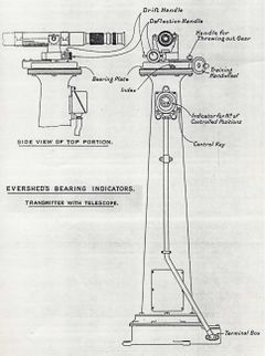
| − | [[File:HandbookFireControl1914Plate34.jpg|thumb|240px|'''Transmitter with Telescope'''<br>As might be located aloft. | + | [[File:HandbookFireControl1914Plate34.jpg|thumb|240px|'''Transmitter with Telescope'''<br>As might be located aloft.{{HFCI1914|Plate 34}} ]] |
| − | The Royal Navy found with experience that it was very difficult to ensure that all pertinent positions shared a common understanding of what target was to be fired upon or illuminated by searchlight. Even though a [[Gunnery Director|director]] was a fairly sure means of getting all the guns to fire upon the same target, there was no guarantee that the director would choose the target the [[Gunnery Officer]] intended. The Evershed system helped considerably, and efforts to increase the number and thoroughness of installations were a priority. | + | The Royal Navy found with experience that it was very difficult to ensure that all pertinent positions shared a common understanding of what target was to be fired upon or illuminated by searchlight. Even though a [[Gunnery Director|director]] was a fairly sure means of getting all the guns to fire upon the same target, there was no guarantee that the director would choose the target the [[Gunnery Officer]] intended. The Evershed system helped considerably, and efforts to increase the number and thoroughness of installations were a priority.{{FCHMShips|p. 29}} |
| − | By | + | By June, 1914, all Dreadnought battleships and battle cruisers, except the [[Iron Duke Class Battleship (1912)|''Iron Duke'' class]], [[H.M.S. Audacious (1912)|''Audacious'']], [[H.M.S. Ajax (1912)|''Ajax'']] and [[H.M.S. Queen Mary (1912)|''Queen Mary'']], had been fitted with Evershed's according to the [[Director of Naval Ordnance and Torpedoes (Royal Navy)|Director of Naval Ordnance]], Captain [[Frederick Charles Tudor Tudor|Frederick C. T. Tudor]].<ref>"Important Questions Dealt with by D.N.O." '''III'''. ff. 637-638. Naval Historical Branch. This source appears to directly contradict Brooks. ''Fire Control for British Dreadnoughts''. p. 62.</ref> They had Evershed transmitters in the primary control position for the main battery or in their [[Gun Control Tower]] (if they had one), and ships with 6-in secondary batteries had transmitters in both day and night control positions.{{CN}} At the [[Battle of Dogger Bank]], the systems were deemed "invaluable".{{GFGTO|No. 51}} |
| − | + | ||
| − | In | + | In 1916, those ships with {{GCT}}s but with primary control positions in their tops had transmitters added to their tops.{{FCHMShips|p. 29}} |
| − | + | In September 1916, some ships were given "Captain's Local Control" installations so the captain could show the control officer onto the intended target. These installations placed transmitters in the [[Conning Tower]] (later, also at the [[Bridge]]). Presumably, there were receivers at the primary and possibly the secondary [[Control Position|control positions]].{{FCHMShips|p. 29}} | |
| − | By 1916, main and secondary armament directors which did not already have receivers were fitted (or ordered to be fitted?) The next application was [[Torpedo Control|torpedo control]], commencing with a July 1917 order to equip 26 capital ships with gear. In October 1917, gear was ordered for (or fitted to??) all rangefinders not in turrets. | + | Similar to the manner with which directors were fitted into smaller and smaller vessels as supplies permitted, in October 1916 light cruisers were next to start receiving Evershed gear, starting with the [[Centaur_Class_Cruiser_(1916)|''Centaur'' class]] and onward. In February 1917, the initiative spread to an order to equip 100 existing ships as well as ships still under construction to include [[Danae_Class_Cruiser_(1917)|''Danae'' class]] and later with equipment for searchlight control.{{FCHMShips|p. 29}} |
| + | |||
| + | By 1916, main and secondary armament directors which did not already have receivers were fitted (or ordered to be fitted?) The next application was [[Torpedo Control|torpedo control]], commencing with a July 1917 order to equip 26 capital ships with gear. In October 1917, gear was ordered for (or fitted to??) all rangefinders not in turrets.{{FCHMShips|pp. 29-30}} | ||
==Technical Analysis== | ==Technical Analysis== | ||
| − | [[File:HandbookFireControl1914Plate36.jpg|thumb|300px|'''Transmitter on Argo Mounting''' | + | [[File:HandbookFireControl1914Plate36.jpg|thumb|300px|'''Transmitter on Argo Mounting'''{{HFCI1914|Plate 36}} ]] |
| − | Much of the detailed working of the devices and their installation in particular ships is recorded in the ''Handbook for Fire Control Instruments, 1914'' | + | Much of the detailed working of the devices and their installation in particular ships is recorded in the ''Handbook for Fire Control Instruments, 1914''{{HFCI1914|Chap VI (pp. 30-42), and Plates 34-48}}. Explanation of the equipment follows, but details on particular installations taken from this rich source are relegated to the articles pertaining to the ship or class of ship in question. |
===Power=== | ===Power=== | ||
| − | Power for an Evershed installation came from a generator powered by an electric motor (called an ''isolator'') which was in turn powered by the ship's mains. A reserve isolator was provided in case of failure. These generators were preferably located near the forward transmitting station | + | Power for an Evershed installation came from a generator powered by an electric motor (called an ''isolator'') which was in turn powered by the ship's mains. A reserve isolator was provided in case of failure. These generators were preferably located near the forward transmitting station{{HFCI1914|p. 31}}. |
===Electrical Principles of Transmission=== | ===Electrical Principles of Transmission=== | ||
| − | The electrical network between transmitters and receivers conveyed the bearing [[Synchronous Transmission|synchronously]] by comparing resistances bridging the circuit at the transmitting and receiving end. Because a circular training arc of 360 degrees offers no ready linear mapping of values (i.e., 30 degrees is obviously to the right of 20 degrees, but 355 degrees is to its ''left''), the solution taken (in {{UK-Dreadnought}} and later-designed ships) was to employ 2 different overlapping arcs of 200 degrees each, and having the transmitter mechanically switch between which was employed and to signal this change by a separate circuit to the receivers | + | The electrical network between transmitters and receivers conveyed the bearing [[Synchronous Transmission|synchronously]] by comparing resistances bridging the circuit at the transmitting and receiving end. Because a circular training arc of 360 degrees offers no ready linear mapping of values (i.e., 30 degrees is obviously to the right of 20 degrees, but 355 degrees is to its ''left''), the solution taken (in {{UK-Dreadnought}} and later-designed ships) was to employ 2 different overlapping arcs of 200 degrees each, and having the transmitter mechanically switch between which was employed and to signal this change by a separate circuit to the receivers{{HFCI1914|pp. 38-9, Plate 40}}. |
| − | A simpler mechanism based on a strict forward/aft control model was used in [[Lord Nelson Class Battleship (1906)|''Lord Nelson'']] and previously designed classes which did not require the change-over | + | A simpler mechanism based on a strict forward/aft control model was used in [[Lord Nelson Class Battleship (1906)|''Lord Nelson'']] and previously designed classes which did not require the change-over{{HFCI1914|pp. 38-9, Plate 40}}. |
===Transmitters=== | ===Transmitters=== | ||
| − | [[File:HandbookFireControl1914Plate35.jpg|thumb|300px|'''Transmitter with Periscope'''<br>As might be located in the GCT. | + | [[File:HandbookFireControl1914Plate35.jpg|thumb|300px|'''Transmitter with Periscope'''<br>As might be located in the GCT.{{HFCI1914|Plate 35}} ]] |
====Location==== | ====Location==== | ||
| Line 38: | Line 39: | ||
Either type could also be connected to periscopes with illuminated cross wires of 5x magnification in the conning and director towers. In some cases, these were single periscopes on the centre line, but sometimes they were paired for port and starboard control with a C.O.S. to select the one in use. | Either type could also be connected to periscopes with illuminated cross wires of 5x magnification in the conning and director towers. In some cases, these were single periscopes on the centre line, but sometimes they were paired for port and starboard control with a C.O.S. to select the one in use. | ||
| − | On some ships with a R.F. mounted on the [[Gun Control Tower|gun control tower]], a Type 2 transmitter would be fitted to transmit the RF's training angle | + | On some ships with a R.F. mounted on the [[Gun Control Tower|gun control tower]], a Type 2 transmitter would be fitted to transmit the RF's training angle{{HFCI1914|p. 30, Plate 36}}. |
====Details==== | ====Details==== | ||
| − | Each transmitter featured a ''control key'' (integrated or simply near-at-hand) which could be set to indicate ''Control'' or ''No Control'' | + | Each transmitter featured a ''control key'' (integrated or simply near-at-hand) which could be set to indicate ''Control'' or ''No Control''{{HFCI1914|Plate 34}}, and this would be signaled to connected receivers. In this way, the indicated bearings could be disassociated from the implied imperative that the receiving station(s) should do anything with the indication, such as train to the same bearing. A tell-tale dial and pointer in the housing showed the number of receiving positions that were connected to this transmitter through the [[#Selector Switch|selector switch]] in the TS{{HFCI1914|p. 32}}. |
When controlling turrets, [[Gun Deflection|deflection]] can be dialed in by a hand-wheel, and a moveable zero allows for entry of [[Drift|drift]] corrections. When no such corrections were in place, the relative bearing of the local optics would be bearing transmitted.<ref>These corrections were necessary, as the receivers at the turrets were not connected to the gun sights, but to the turret; consequently, they would require these lateral deflections to see the target when the turret was correctly oriented for firing on the required deflection. Deflection and drift were separately entered, I think, as not all gun sights had drift correction features and thus the drift would be directed as an increment in the deflections being sent to the guns.</ref> | When controlling turrets, [[Gun Deflection|deflection]] can be dialed in by a hand-wheel, and a moveable zero allows for entry of [[Drift|drift]] corrections. When no such corrections were in place, the relative bearing of the local optics would be bearing transmitted.<ref>These corrections were necessary, as the receivers at the turrets were not connected to the gun sights, but to the turret; consequently, they would require these lateral deflections to see the target when the turret was correctly oriented for firing on the required deflection. Deflection and drift were separately entered, I think, as not all gun sights had drift correction features and thus the drift would be directed as an increment in the deflections being sent to the guns.</ref> | ||
| Line 47: | Line 48: | ||
Type 1 transmitters were fitted to a telescope or periscope with illuminable cross wires. The scope could freely elevate, and could either train freely or by hand-wheel within the arc of control the transmitter was permitted. | Type 1 transmitters were fitted to a telescope or periscope with illuminable cross wires. The scope could freely elevate, and could either train freely or by hand-wheel within the arc of control the transmitter was permitted. | ||
| − | Type 2 had an open-faced indicator for receiving. A peculiarity in design created the possibility that a large difference in signaled versus local bearing might cause the indicator to prompt a change in local bearing in the wrong direction; instruction plates were provided near the indicators to warn of the issue. Only transmitters deployed in port-and-starboard pairs rather than on the centre line that trained toward the quarter were subject to this issue | + | Type 2 had an open-faced indicator for receiving. A peculiarity in design created the possibility that a large difference in signaled versus local bearing might cause the indicator to prompt a change in local bearing in the wrong direction; instruction plates were provided near the indicators to warn of the issue. Only transmitters deployed in port-and-starboard pairs rather than on the centre line that trained toward the quarter were subject to this issue{{HFCI1914|p. 31}}. |
===Receivers=== | ===Receivers=== | ||
| − | [[File:HandbookFireControl1914Plate37.jpg|thumb|350px|'''Evershed Bearing Receiver'''<br>This might be a Type 1 Receiver. | + | [[File:HandbookFireControl1914Plate37.jpg|thumb|350px|'''Evershed Bearing Receiver'''<br>This might be a Type 1 Receiver.{{HFCI1914|Plate 37}} ]] |
Receivers also came in 2 types, with Type 2 being fitted able to transmit as well as receive. Both types displayed the relative bearing by a divided dial and index, not unlike a compass. | Receivers also came in 2 types, with Type 2 being fitted able to transmit as well as receive. Both types displayed the relative bearing by a divided dial and index, not unlike a compass. | ||
| − | Either type of receiver might be fitted in the [[Handing Room|handing room]] and geared to the turret trunks so they would provide a local reading of the training angle | + | Either type of receiver might be fitted in the [[Handing Room|handing room]] and geared to the turret trunks so they would provide a local reading of the training angle{{HFCI1914|p. 30, Plate 37}}. They were also wired to indicators in the gun house{{HFCI1914|p. 32.<br>I am not sure what is meant by this!}}. Those ships employing a Type 2 receiver for this purpose had a control key mounted in the centre sighting position near the trainer so he could choose ''Control'' or ''No Control''. |
===Indicators=== | ===Indicators=== | ||
| − | [[File:HandbookFireControl1914Plate38.jpg|thumb|400px|'''Evershed Type 1 and Type 2 Bearing Indicators''' | + | [[File:HandbookFireControl1914Plate38.jpg|thumb|400px|'''Evershed Type 1 and Type 2 Bearing Indicators'''{{HFCI1914|Plate 38}} ]] |
The indicators were the key to the Evershed equipment, and their name's subtle difference from "receiver" is that they gave a simpler answer than a relative bearing expressed in degrees. Instead, a galvanometer moved a pointer to right or left of a central zero mark, indicating in which direction the operator was to adjust his training to chase the transmitted bearing. As he neared the correct training, the pointer would swing to the center mark, indicating the local position was within 1 degree if the transmitted bearing. | The indicators were the key to the Evershed equipment, and their name's subtle difference from "receiver" is that they gave a simpler answer than a relative bearing expressed in degrees. Instead, a galvanometer moved a pointer to right or left of a central zero mark, indicating in which direction the operator was to adjust his training to chase the transmitted bearing. As he neared the correct training, the pointer would swing to the center mark, indicating the local position was within 1 degree if the transmitted bearing. | ||
| − | Type 1 indicators were for use by trainers in turrets, fitted under the central sighting hood on the right hand sight of the left gun; the operator could look into the indicator with his left eye while his right was on his sighting scope | + | Type 1 indicators were for use by trainers in turrets, fitted under the central sighting hood on the right hand sight of the left gun; the operator could look into the indicator with his left eye while his right was on his sighting scope{{HFCI1914|pp. 30-1 and Plate 38 (fig 1)}}. The indicator, however, was illuminated only when the transmitter's control key was in ''Control'', and was otherwise invisible. An adjustment knob allowed the operator to adjust the intensity of the illumination to suit himself{{HFCI1914|pp. 32 and Plate 38 (fig 1)}}. |
| − | Type 2 indicators were open-faced for greater general visibility. They would be situated near the officer's position within a turret so he could verify the trainer's work, and in those transmitting positions that were also required to receive | + | Type 2 indicators were open-faced for greater general visibility. They would be situated near the officer's position within a turret so he could verify the trainer's work, and in those transmitting positions that were also required to receive{{HFCI1914|pp. 30-1 and Plate 38 (fig 2)}}. A flag at the top of the device read either ''On'' or ''Off'' to indicate whether the transmitter had engaged his control key{{HFCI1914|pp. 32}}. |
===Selector Switch=== | ===Selector Switch=== | ||
| − | [[File:HandbookFireControl1914Plate39.jpg|thumb|350px|'''Selector Switch'''<br>As would be found in the TS of ''King George V.'' | + | [[File:HandbookFireControl1914Plate39.jpg|thumb|350px|'''Selector Switch'''<br>As would be found in the TS of ''King George V.''{{HFCI1914|Plate 39}} ]] |
A ship with a number of transmitting and receiving stations required a switching matrix to dictate which receivers were connected to which transmitters (or not connected). | A ship with a number of transmitting and receiving stations required a switching matrix to dictate which receivers were connected to which transmitters (or not connected). | ||
| Line 88: | Line 89: | ||
==Alternative Applications== | ==Alternative Applications== | ||
| − | [[File:ARTS1916Plate61.jpg|thumb|300px|'''Evershed Bearing Receiver for Searchlight Control''' | + | [[File:ARTS1916Plate61.jpg|thumb|300px|'''Evershed Bearing Receiver for Searchlight Control'''{{ARTS1916|Plate 61}} ]] |
| − | In 1916, the system was being fitted to various ships to help searchlights find their target. There was a comfort factor in the technology and its provider, but an alternative system from ''Vernon'' which used low voltage and could use multicore telephone cables was being tested at the same time. | + | In 1916, the system was being fitted to various ships to help searchlights find their target. There was a comfort factor in the technology and its provider, but an alternative system from ''Vernon'' which used low voltage and could use multicore telephone cables was being tested at the same time.{{ARTS1916|p. 135}} |
==See Also== | ==See Also== | ||
| Line 101: | Line 102: | ||
{{refbegin}} | {{refbegin}} | ||
*{{HFCI1914}} | *{{HFCI1914}} | ||
| − | *{{ | + | *{{FCHMShips}} |
| + | *{{BrooksThesis}} | ||
{{refend}} | {{refend}} | ||
[[Category:Fire Control]] | [[Category:Fire Control]] | ||
[[Category:Shipboard Equipment]] | [[Category:Shipboard Equipment]] | ||
Latest revision as of 06:51, 21 October 2022
Evershed's Bearing Indicators were a family of transmitters, receivers and indicators designed to communicate throughout the ship a target's relative bearing so that guns and/or searchlights could be trained upon it. Generally, the granularity of the bearings as read off the indicators was only sufficient (accurate to within 1 degree[1]) to establish a shared understanding of which ship was the target. In this way, the devices were really a check against problems such as a rangefinder ranging against the wrong ship or the spotter observing and reporting on another ship's fire.
Contents
History and Deployment
The Royal Navy found with experience that it was very difficult to ensure that all pertinent positions shared a common understanding of what target was to be fired upon or illuminated by searchlight. Even though a director was a fairly sure means of getting all the guns to fire upon the same target, there was no guarantee that the director would choose the target the Gunnery Officer intended. The Evershed system helped considerably, and efforts to increase the number and thoroughness of installations were a priority.[3]
By June, 1914, all Dreadnought battleships and battle cruisers, except the Iron Duke class, Audacious, Ajax and Queen Mary, had been fitted with Evershed's according to the Director of Naval Ordnance, Captain Frederick C. T. Tudor.[4] They had Evershed transmitters in the primary control position for the main battery or in their Gun Control Tower (if they had one), and ships with 6-in secondary batteries had transmitters in both day and night control positions.[Citation needed] At the Battle of Dogger Bank, the systems were deemed "invaluable".[5]
In 1916, those ships with G.C.T.s but with primary control positions in their tops had transmitters added to their tops.[6]
In September 1916, some ships were given "Captain's Local Control" installations so the captain could show the control officer onto the intended target. These installations placed transmitters in the Conning Tower (later, also at the Bridge). Presumably, there were receivers at the primary and possibly the secondary control positions.[7]
Similar to the manner with which directors were fitted into smaller and smaller vessels as supplies permitted, in October 1916 light cruisers were next to start receiving Evershed gear, starting with the Centaur class and onward. In February 1917, the initiative spread to an order to equip 100 existing ships as well as ships still under construction to include Danae class and later with equipment for searchlight control.[8]
By 1916, main and secondary armament directors which did not already have receivers were fitted (or ordered to be fitted?) The next application was torpedo control, commencing with a July 1917 order to equip 26 capital ships with gear. In October 1917, gear was ordered for (or fitted to??) all rangefinders not in turrets.[9]
Technical Analysis
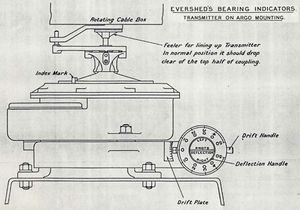
Much of the detailed working of the devices and their installation in particular ships is recorded in the Handbook for Fire Control Instruments, 1914[11]. Explanation of the equipment follows, but details on particular installations taken from this rich source are relegated to the articles pertaining to the ship or class of ship in question.
Power
Power for an Evershed installation came from a generator powered by an electric motor (called an isolator) which was in turn powered by the ship's mains. A reserve isolator was provided in case of failure. These generators were preferably located near the forward transmitting station[12].
Electrical Principles of Transmission
The electrical network between transmitters and receivers conveyed the bearing synchronously by comparing resistances bridging the circuit at the transmitting and receiving end. Because a circular training arc of 360 degrees offers no ready linear mapping of values (i.e., 30 degrees is obviously to the right of 20 degrees, but 355 degrees is to its left), the solution taken (in Dreadnought and later-designed ships) was to employ 2 different overlapping arcs of 200 degrees each, and having the transmitter mechanically switch between which was employed and to signal this change by a separate circuit to the receivers[13].
A simpler mechanism based on a strict forward/aft control model was used in Lord Nelson and previously designed classes which did not require the change-over[14].
Transmitters
Location
Each transmitter was generally connected to a periscope or telescope in a control position, and it would transmit the training angle of the host optical device. There were 2 types of transmitters, Type 1 and Type 2, with Type 2 also having the ability to receive.
Transmitters of either type were often found in the fore top in pairs to port and starboard, connected to sighting telescopes on pedestals. A local C.O.S. permitted a choice of which transmitter would be in service and connected to the output cables.
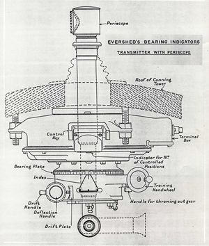
Either type could also be connected to periscopes with illuminated cross wires of 5x magnification in the conning and director towers. In some cases, these were single periscopes on the centre line, but sometimes they were paired for port and starboard control with a C.O.S. to select the one in use.
On some ships with a R.F. mounted on the gun control tower, a Type 2 transmitter would be fitted to transmit the RF's training angle[16].
Details
Each transmitter featured a control key (integrated or simply near-at-hand) which could be set to indicate Control or No Control[17], and this would be signaled to connected receivers. In this way, the indicated bearings could be disassociated from the implied imperative that the receiving station(s) should do anything with the indication, such as train to the same bearing. A tell-tale dial and pointer in the housing showed the number of receiving positions that were connected to this transmitter through the selector switch in the TS[18].
When controlling turrets, deflection can be dialed in by a hand-wheel, and a moveable zero allows for entry of drift corrections. When no such corrections were in place, the relative bearing of the local optics would be bearing transmitted.[19]
Type 1 transmitters were fitted to a telescope or periscope with illuminable cross wires. The scope could freely elevate, and could either train freely or by hand-wheel within the arc of control the transmitter was permitted.
Type 2 had an open-faced indicator for receiving. A peculiarity in design created the possibility that a large difference in signaled versus local bearing might cause the indicator to prompt a change in local bearing in the wrong direction; instruction plates were provided near the indicators to warn of the issue. Only transmitters deployed in port-and-starboard pairs rather than on the centre line that trained toward the quarter were subject to this issue[20].
Receivers
Receivers also came in 2 types, with Type 2 being fitted able to transmit as well as receive. Both types displayed the relative bearing by a divided dial and index, not unlike a compass.
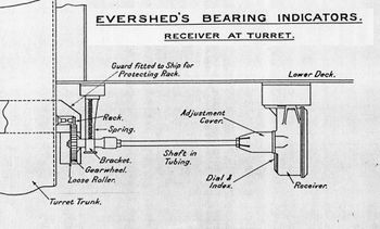
Either type of receiver might be fitted in the handing room and geared to the turret trunks so they would provide a local reading of the training angle[22]. They were also wired to indicators in the gun house[23]. Those ships employing a Type 2 receiver for this purpose had a control key mounted in the centre sighting position near the trainer so he could choose Control or No Control.
Indicators
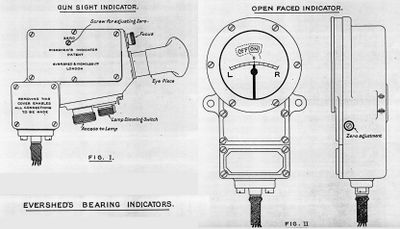
The indicators were the key to the Evershed equipment, and their name's subtle difference from "receiver" is that they gave a simpler answer than a relative bearing expressed in degrees. Instead, a galvanometer moved a pointer to right or left of a central zero mark, indicating in which direction the operator was to adjust his training to chase the transmitted bearing. As he neared the correct training, the pointer would swing to the center mark, indicating the local position was within 1 degree if the transmitted bearing.
Type 1 indicators were for use by trainers in turrets, fitted under the central sighting hood on the right hand sight of the left gun; the operator could look into the indicator with his left eye while his right was on his sighting scope[25]. The indicator, however, was illuminated only when the transmitter's control key was in Control, and was otherwise invisible. An adjustment knob allowed the operator to adjust the intensity of the illumination to suit himself[26].
Type 2 indicators were open-faced for greater general visibility. They would be situated near the officer's position within a turret so he could verify the trainer's work, and in those transmitting positions that were also required to receive[27]. A flag at the top of the device read either On or Off to indicate whether the transmitter had engaged his control key[28].
Selector Switch
A ship with a number of transmitting and receiving stations required a switching matrix to dictate which receivers were connected to which transmitters (or not connected).
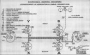
A selector switch (actually, a switchboard) located in the forward TS enabled any receiving position (those containing any type of receiver or a Type 2 transmitter) to be connected to any transmitting position (those containing any type of transmitter or a Type 2 receiver). Each receiving station was represented by a rotary handle that could be clicked to a numbered position representing which transmitting station (or none at all) it should be connected to. This system provided the means for one transmitting position to send to 0 or more receiving positions, and each receiving position could connect to 0 or 1 transmitting position.
Those positions capable of both transmitting and receiving (i.e., those with a Type 2 receiver or a Type 2 transmitter) would generally have the knob representing their receiver switched to an off position. One exception cited was that a transmitting position might monitor the transmissions of another position in case it lost sight of the target, in which case it was permitted to match the indications of the station it was monitoring and thereby pass them on to its switched-in receivers. However, this daisy-chaining could not be repeated to another stage.
Refinements and Improvements
There were few changes made to the design during the war:[30]
- Smaller receivers were created for use at secondary armament guns after larger ones were found to be unsatisfactory in Tiger and Marlborough.
- Binocular transmitters were given worm training gear to prevent being knocked off-kilter by blast (December 1917)
- Automatic mechanisms to provide convergence in training (for searchlight control only, apparently)
- Provision of electrical means of applying or removing deflection so that gun directors could be used for searchlight control.
Sample Installations
The Handbook for Fire Control Instruments, 1914 richly illustrates the entire Evershed installation for several classes of capital ship.
Alternative Applications
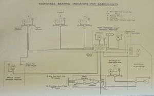
In 1916, the system was being fitted to various ships to help searchlights find their target. There was a comfort factor in the technology and its provider, but an alternative system from Vernon which used low voltage and could use multicore telephone cables was being tested at the same time.[32]
See Also
Footnotes
- ↑ Handbook for Fire Control Instruments, 1914. p. 32.
- ↑ Handbook for Fire Control Instruments, 1914. Plate 34.
- ↑ The Technical History and Index, Vol. 3, Part 23. p. 29.
- ↑ "Important Questions Dealt with by D.N.O." III. ff. 637-638. Naval Historical Branch. This source appears to directly contradict Brooks. Fire Control for British Dreadnoughts. p. 62.
- ↑ Grand Fleet Gunnery and Torpedo Orders. No. 51.
- ↑ The Technical History and Index, Vol. 3, Part 23. p. 29.
- ↑ The Technical History and Index, Vol. 3, Part 23. p. 29.
- ↑ The Technical History and Index, Vol. 3, Part 23. p. 29.
- ↑ The Technical History and Index, Vol. 3, Part 23. pp. 29-30.
- ↑ Handbook for Fire Control Instruments, 1914. Plate 36.
- ↑ Handbook for Fire Control Instruments, 1914. Chap VI (pp. 30-42), and Plates 34-48.
- ↑ Handbook for Fire Control Instruments, 1914. p. 31.
- ↑ Handbook for Fire Control Instruments, 1914. pp. 38-9, Plate 40.
- ↑ Handbook for Fire Control Instruments, 1914. pp. 38-9, Plate 40.
- ↑ Handbook for Fire Control Instruments, 1914. Plate 35.
- ↑ Handbook for Fire Control Instruments, 1914. p. 30, Plate 36.
- ↑ Handbook for Fire Control Instruments, 1914. Plate 34.
- ↑ Handbook for Fire Control Instruments, 1914. p. 32.
- ↑ These corrections were necessary, as the receivers at the turrets were not connected to the gun sights, but to the turret; consequently, they would require these lateral deflections to see the target when the turret was correctly oriented for firing on the required deflection. Deflection and drift were separately entered, I think, as not all gun sights had drift correction features and thus the drift would be directed as an increment in the deflections being sent to the guns.
- ↑ Handbook for Fire Control Instruments, 1914. p. 31.
- ↑ Handbook for Fire Control Instruments, 1914. Plate 37.
- ↑ Handbook for Fire Control Instruments, 1914. p. 30, Plate 37.
- ↑ Handbook for Fire Control Instruments, 1914. p. 32.
I am not sure what is meant by this!. - ↑ Handbook for Fire Control Instruments, 1914. Plate 38.
- ↑ Handbook for Fire Control Instruments, 1914. pp. 30-1 and Plate 38 (fig 1).
- ↑ Handbook for Fire Control Instruments, 1914. pp. 32 and Plate 38 (fig 1).
- ↑ Handbook for Fire Control Instruments, 1914. pp. 30-1 and Plate 38 (fig 2).
- ↑ Handbook for Fire Control Instruments, 1914. pp. 32.
- ↑ Handbook for Fire Control Instruments, 1914. Plate 39.
- ↑ The Technical History and Index: Fire Control in HM Ships, p. 30.
- ↑ Annual Report of the Torpedo School, 1916. Plate 61.
- ↑ Annual Report of the Torpedo School, 1916. p. 135.
Bibliography
- Admiralty, Gunnery Branch (1914). Handbook for Fire Control Instruments, 1914. G. 01627/14. C.B. 1030. Copy 1235 at The National Archives. ADM 186/191.
- Admiralty, Technical History Section (1919). The Technical History and Index: Fire Control in H.M. Ships. Vol. 3, Part 23. C.B. 1515 (23) now O.U. 6171/14. At The National Archives. ADM 275/19.
- Brooks, John (2001). Fire Control for British Dreadnoughts: Choices of Technology and Supply. Unpublished PhD Thesis. London: Department of War Studies. King's College, London.
