Drift
Drift is a ballistic phenomenon that causes a spinning projectile (such as a shell fired from a rifled gun) to be pulled laterally in the direction of the spin (as seen at the top of the shell) as it flies down range.
Character
The Royal Navy found that for any given gun, the shell would drift a distance that was proportional to the square of the Time-of-flight, and thus was as if a constant force was pushing the shell laterally as it flew. It would calculate the amount of force for the given gun and then create sighting equipment that could correct (exactly, or approximately) this by adding deflection to the gun sights as range was dialed on.
It is not easy to find comprehensible information on ballistic drift as a physical phenomenon. Indeed, it is hard to find specific data on a given gun system for how far the shell would deviate laterally (generally to the right, given the customary direction of twist in rifling) as it traveled to various ranges. However, the 1918 Range Tables offer a little explanation for how the Royal Navy treated drift and some of the compiled range tables within include fairly complete drift data, although one might be suspicious as to which are experimentally obtained and which are the result of a mathematical model for drift.
It was observed that the length of the projectile was a primary factor for why different shells exhibited different drift behaviors[1], and a mathematical description of drift angles was derived for use in the form:
driftAngle = someConstantForThisGunAndProjectile * tangent(elevation)[2]
However, not all range tables within the volume have drift expressed in this manner, as determination of the constant for all guns was not possible before going to press.[3] The formula is puzzling, as it seems as though not only was a rule of thumb being entrusted to model drift for the world's pre-eminent navy, but that it had been recently conceived and relied upon empirical constants still being sorted out.
Critical thought indicates that the formula might not express the drift angles observed in test firings, but those allowances for drift provided by the Royal Navy's oft-employed mechanical drift correction built into many of her gun sight apparatuses wherein the sights and their scopes were simply cocked to the side a degree or two so that as the gun was elevated a deflection was progressively induced. It is not clear, then, whether the drift data in the volume are results taken from this formula and why range tables did not include drift data based on a few test firings at different ranges and with other values plugged in after interpolating their likely best values.
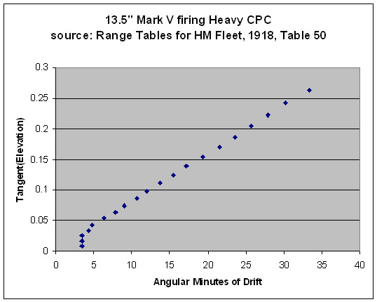
Ignoring for the moment our doubts as to where these data came from, a graphical analysis of the drift data from one range table (Table 50) does not seem to imply that it was spat out by the RN's drift angle formula. One caveat is that the first few data are likely distorted due to rounding errors, as the first 5 appear with only a single significant digit. This first scatter plot explores the correlation between the RN's formula and the data in the table.
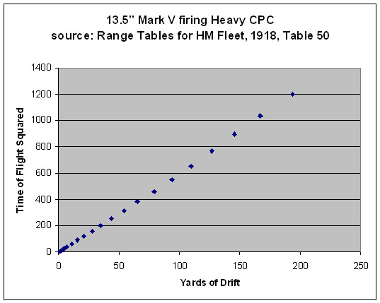
The correlation seems fair, but a visual inspection clearly indicates a relatively weak relationship at the short range shots. Let us ignore the Royal Navy's best published thinking on the matter and work with a hypothesis that the lateral deviation observed in practice was the result of a constant force acting upon the shell throughout its flight, and that maybe the data in this one table are derived from actual test firings (possibly with some interpolation). This seems like a reach, but proves a gamble well worth taking: we achieve an even better fit, even when including the first 11 data points with their presumed rounding errors!
The conclusion is that extremely faithful simulation of drift can be attained by taking the most extreme (range, time-of-flight, drift) datum available for a gun/charge/projectile system and calculating a constant lateral force which, if applied continually during flight that produces the drift behavior observed in this single historical firing. A big win for the anal retentive game coder who lacks a PhD in Physics.
Correction of Drift
One simple (but substantially correct) treatment for drift was to incline the gun sights as they were fitted onto the gun by cocking them (rolling them, as you look downrange) a bit to the left. In this way, as range was dialed on and the sights depressed, they'd also yaw a bit to the right (the direction of drift with the guns rifled rightward). This would require the trainer to train a bit more left. The effect was to bring the shells back on for drift at the given range. This was a fair approximation, and the imperfection was deemed acceptable in most cases. Even so, the presence of a column labelled "Uncorrected Drift" on the Deflection Totaliser created for the Dreyer Fire Control Table seems to suggest that it might have been used to enter in this error so it, too, would be corrected, though it is likely that it was really intended to be used when 6 degree elevation prisms were fitted on the director.
See Also
Footnotes
Bibliography
- Admiralty, Gunnery Branch (1907). Manual of Gunnery (Volume I. Part I.) for His Majesty's Fleet, 1907. (G. 4117/1907) Copy No. 783 is Ja. 254 at Admiralty Library, Portsmouth.

