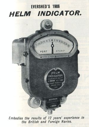
Evershed Helm Indicator
Evershed's Helm Indicator was an electro-mechanical shipboard instrument which provided a visual indication of the tiller position. They were often mounted on the bridge or in the conning tower. It was in service in "a number of ships" of the Royal Navy in 1905 and likely earlier.[1]
A transmitter was fitted at the rudder head and wiring laid the receivers (in 1905, one was located on the bridge and another in the conning tower). They were "ratio coil" instruments based on having a magnetic needle always position itself in line with the strongest magnetic field. This design made them entirely synchronous and seems a common approach to that taken in the Evershed's Bearing Indicator.
"These two receivers are connected in parallel, and either may be used as desired by switching it on with a three-way switch placed in the conning tower."[2]
In 1903, a lamp and rheostat as used in night sights was introduced for the indicator.[3] The instrument was to be kept switched off when not in use, and stress was laid upon checking its indication upon first being turned on, and occasionally in regular use. If the device was found to be out of adjustment, a brass cap could be removed from the receiver and a switch within it turned a bit.
Refinements
By 1908, an improved model was offered which "embodies the same electrical principle as the old one, but the ratio of the two currents is altered in a different manner." This device reduced the generation of an unwanted magnetic field, possibly allowing the adjusting mechanism of the old model to be eliminated,[4] but by 1912, mention is made of what might only be a simpler adjustment mechanism at the receiver: the name plate could be lifted up and a screw worked to adjust the receiver pointer by 2.5 degrees either way. A two-way power switch on the receiver allowed "no power to be kept on the receiver which is not being used."[5]
See Also
Footnotes
Bibliography
- Template:BibUKTorpedoDrillBook1905
- Template:BibUKTorpedoDrillBook1908
- Template:BibUKTorpedoDrillBook1912


