Caledon Class Cruiser (1916): Difference between revisions
(replace "[[Scott" with "[[Scotts Shipbuilding and Engineering Company") |
m (→Torpedoes) |
||
| Line 59: | Line 59: | ||
===Torpedoes=== | ===Torpedoes=== | ||
* | * four [[21-in D.R. Torpedo Tube (UK)|21-in D.R. torpedo tubes]] (4x2) disposed in pairs abreast, bearing 60-120 degrees. | ||
As the 6-in guns fired over these, they proved untenable for manned firing as the 6-in guns would have necessitated a blast shield projecting fully 18 feet from the muzzle. The ugly expedient taken was to train the tubes to a pre-arranged bearing on coming to action stations and to use remote firing from the primary and secondary control positions.{{ARTS1916|p. 35}} | As the 6-in guns fired over these, they proved untenable for manned firing as the 6-in guns would have necessitated a blast shield projecting fully 18 feet from the muzzle. The ugly expedient taken was to train the tubes to a pre-arranged bearing on coming to action stations and to use remote firing from the primary and secondary control positions.{{ARTS1916|p. 35}} | ||
Revision as of 13:04, 13 July 2019
The four light cruisers of the Caledon Class were completed in 1917.
In contemporary documents, often referred to as the Calypso Class.
| Overview of 4 vessels | |||||
|---|---|---|---|---|---|
| Citations for this data available on individual ship pages | |||||
| Name | Builder | Laid Down | Launched | Completed | Fate |
| Caledon | Cammell Laird | 17 Mar, 1916 | 25 Nov, 1916 | Mar, 1917 | Sold Jan, 1948 |
| Calypso | Hawthorn Leslie & Company | 7 Feb, 1916 | 24 Jan, 1917 | Jun, 1917 | Torpedoed 12 Jun, 1940 |
| Caradoc | Scotts Shipbuilding and Engineering Company | 21 Feb, 1916 | 23 Dec, 1916 | Jun, 1917 | Sold Apr, 1946 |
| Cassandra | Vickers | Mar, 1916 | 25 Nov, 1916 | Jun, 1917 | Mined 5 Dec, 1918 |
Machinery
Generators
In 1916, it was stated that ""C" and "D" class light cruisers" have three 52.5 kw dynamos at 105 volts.[1]
Armament
The ships were armed as follows.[2]
Guns
- Five 6-in 45cal B.L. Mark XII guns on P. XIII* mountings on the centre-line with a maximum elevation of 30 degrees.[3][4] The guns had armoured shields of 1/4 inch on the face, 3/16 inch on sides and top, weighing 1.25 tons.[5]
- Two 3-in 20cwt Q.F. on H.A. mountings
- Four 3-pdr
Torpedoes
- four 21-in D.R. torpedo tubes (4x2) disposed in pairs abreast, bearing 60-120 degrees.
As the 6-in guns fired over these, they proved untenable for manned firing as the 6-in guns would have necessitated a blast shield projecting fully 18 feet from the muzzle. The ugly expedient taken was to train the tubes to a pre-arranged bearing on coming to action stations and to use remote firing from the primary and secondary control positions.[6]
Fire Control
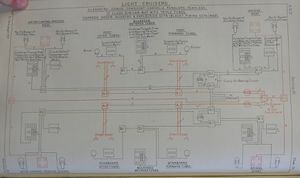
Arrangements were likened to those in the Centaur class, except that:[7]
- the T.S. had a single master push for firing gongs as opposed to one for each group
- the navyphone exchange in the T.S. is a 20-line board (rather than a 15-line board as in Centaur) with a Pattern 3331 in the C.T. connected to it.
- a C.O.S. in the gun director tower can connect the main or aux firing circuits to the Henderson Firing Gear, in line with general adoption of this equipment in all ships with director firing
Mechanical Aid-to-Spotter
By 1920, the three surviving ships were likely equipped with Mechanical Aid-to-Spotter Mark II*s with Evershed Bearing Transmitters.[8] The installations generally consisted of placing one on each side of the foretop, driven by flexible shafting from a gearbox on the director tower.[9]
Supplies of these devices began in June 1918.[10]
Range Dials
In 1918, it was ordered that these and ten other classes of light cruisers should receive "range instruments for concentration of fire". Presumably, this meant range dials.[11]
As of 1920, the three surviving ships had two Range Dial Type Cs with 10 foot dials and a single Range Dial Type L.[12]
Rangefinders
Sometime during or after 1917, an additional 9-foot rangefinder was to be added specifically to augment torpedo control.[13]
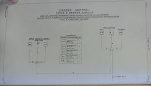
By June 1918, it was determined that the ships would probably eventually carry three 12-foot rangefinders, two forward and one aft.[14] It was also decided that the existing range transmitter on the fore control platform was to be used to transmit ranges from the port rangefinder forward to the T.S., fore top, and aft torpedo control position while that on the rangefinder on the aft torpedo control position was to be moved to moved to allow the starboard forward rangefinder to transmit to the same three locations. [15]
Evershed Bearing Indicators
These ships may have had Evershed gear for gun control from delivery, as this feature for light cruisers was inaugurated by the Centaur class. The approval for their outfits was issued in 1916.[16]
Orders for Evershed installations for searchlight control from February 1917 first applied to the Danae class, but may not have applied to Caledon.[17]
Gunnery Control
Control Positions
Control Groups
Guns 1 through 3 were a group and guns 4 and 5 a separate control group.[18]
The T.S. had a 3 position C.O.S. for firing, elevation and training signals:
- all guns on director tower
- all guns on #4 directing gun
- guns #1 - 3 on director tower, guns #4 and 5 on directing gun
Directors

All ships were completed with gunnery directors in place on the tripod foremast.[20] The director was in a tower on a pedestal mounting and was augmented by use of their "X" (or number 4) gun as a directing gun.[21]
Each gun had a local C.O.S. to switch it between director and local firing. Seemingly, these were 2-position, director or local, and lacking the customary option to cross-over the local main and aux pistols and circuits. The gunnery director tower had 3 firing pistols, main, auxiliary and "local", and a 3-position C.O.S. to govern their behavior. It is not apparent to the editor what the "local" pistol did.[22]
The director was powered by either of a pair of motor alternators, with a C.O.S. available to choose which was to be used.[23]
Calypso and Caradoc had 6-in P. XIII Type Elevation Receivers with electrical tilt correction capable of indicating 30 degrees elevation, Pattern V.E. 1. Caledon and Cassandra had 4-in Triple Type receivers with mechanical tilt correction capable of indicating 30 degrees elevation, Pattern H. 16. The Small Type Training Receivers on all were pattern number 20 on #1, #2 and #3, whereas #4 and #5 had pattern number 21.[24]
Transmitting Stations
Other than the control details mentioned above, no information on its equipment is available. Presumably, there was at least a range clock, dumaresq, and range and deflection transmitters, and likely in pairs to match the control grouping provided for director firing.
Dreyer Table
These ships had no fire control tables.[25]
Fire Control Instruments
Torpedo Control


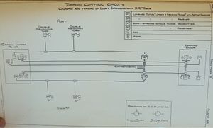
The Ceres and Caledon classes were similar in having a roofless forward control position before and below the compass platform rather than in the C.T. where space was too limited. The torpedo control communications did not provide a means for repeating orders from tubes to control positions. Voicepipes were provided from compass platform to tubes, but in late 1917, these were to be augmented by navyphones, as the voicepipes were proving unreliable given the distance and the presence of an extension between aft control and aft tubes. New stop-cocks to isolate this long voicepipe were being tried in 1917. [29]
In 1916, it was decided that all light cruisers of Bristol class and later should have torpedo firing keys (Pattern 2333) fitted on the fore bridge, in parallel with those in the C.T., and that a flexible voice pipe be fitted between these positions. [30]
Additionally, all light cruisers with submerged tubes were to receive torpedo order and gyro angle instruments between torpedo flats and both control positions. The C class (which may or may not encompass the Caledon class) was to receive Chadburn's Torpedo Telegraphs to meet this need. Otherwise, Barr and Stroud would be a likely choice.[31]
The forward and the after control position were equipped with combined deflection, order and bearing transmitters with telltale and receivers, Graham type, Mark I, which connected through C.O.S.es in the T.S. to the crew's shelter positions near the tubes. The aft T.C.P. had a Barr and Stroud Mark III range transmitter wired to a receiver in the forward control position, and both control positions had fire gongs to the tubes. The forward had voice pipes to the after T.C.P., and both positions had pipes to the tubes. Both T.C.P.s also had Electro-Pneumatic Firing Gear to the tubes.[32]
In 1916, torpedo control lessons pertinent to the equipment of light cruisers and destroyers that had been taken from experience the Battle of Jutland were to be apply to light cruisers "of Penelope class and later". The baseline capabilities required that primary control be exercised from the fore bridge, where Fore Bridge Firing Gear and a sight or director would be fitted, and that this position should enjoy efficient communication to a similar secondary position located some distance away. Additionally, the ships would need:
- Fore Bridge Firing Gear
- order instruments from control positions to A.W. tubes
- deflection instruments
- fire gongs and alarm gongs
The A.W. tubes were to have local sights fitted, and the tubes should enjoy order and sightsetting instruments from the control positions as well as firing gongs in case fore bridge firing should fail. [33]
This work was still underway in the various light cruisers as of early 1918.[34]
By 1917, modifications to the torpedo control voice pipe system were desired. The voice pipes (port and starboard) to the forward were ordered to be removed in 1917, and in 1918, stop cocks were to be added just abaft the after torpedo positions to allow the after control position to be chopped out to improve the acoustic efficiency of the networks to remaining the rangefinder platform control position forward. [35]
In mid-1920, it was decided that the three surviving ships in this class should each receive a Renouf Torpedo Tactical Instrument Type A.[36]
See Also
Footnotes
- ↑ Annual Report of the Torpedo School, 1916. p. 120.
- ↑ Conway's All the World's Fighting Ships 1906–1921. p. 60.
- ↑ Progress in Naval Gunnery, 1914-1918", p. 10.
- ↑ The Director Firing Handbook. p. 144.
- ↑ The Technical History and Index, Vol. 4, Part 34. p. 18. I presume the described ""C" class" pertains to these ships.
- ↑ Annual Report of the Torpedo School, 1916. p. 35.
- ↑ The Director Firing Handbook. p. 150. Centaur class arrangements described in Annual Report of the Torpedo School, 1915, pp. 240-241 which I lack, and diagrammed in ARTS 1916 Plates 77-78.
- ↑ Manual of Gunnery for H.M. Ships, Volume III, 1920, p. 35.
- ↑ Manual of Gunnery (Volume III) for His Majesty's Fleet, 1920. p. 35, 37.
- ↑ The Technical History and Index, Vol. 3, Part 23. pp. 25-6.
- ↑ Annual Report of the Torpedo School, 1918. p. 376. (C.I.O. 3492/18, N.S. 11226/18).
- ↑ Manual of Gunnery (Volume III) for His Majesty's Fleet, 1920. p. 45.
- ↑ Annual Report of the Torpedo School, 1917. p. 199. (possibly pertinent: C.I.O. 481/17).
- ↑ Grand Fleet Gunnery and Torpedo Orders. 21/6/1918, p. 116.
- ↑ Annual Report of the Torpedo School, 1918. p. 179 (A.L.G. 4657/18).
- ↑ The Technical History and Index, Vol. 3, Part 23. p. 29, Annual Report of the Torpedo School', 1916', p. 175.
- ↑ The Technical History and Index, Vol. 3, Part 23. p. 29.
- ↑ The Director Firing Handbook. Plate 82.
- ↑ The Director Firing Handbook. Plate 82.
- ↑ The Technical History and Index, Vol. 3, Part 23. p. 11.
- ↑ Handbook of Captain F. C. Dreyer's Fire Control Tables, 1918. p. 142 and plate opposite.
- ↑ The Director Firing Handbook. Plate 82.
- ↑ The Director Firing Handbook. Plate 82.
- ↑ The Director Firing Handbook. pp. 144-146.
- ↑ Handbook of Captain F. C. Dreyer's Fire Control Tables, 1918. p. 3.
- ↑ Annual Report of the Torpedo School, 1916. Plate 86.
- ↑ Annual Report of the Torpedo School, 1917. Plate 75.
- ↑ Annual Report of the Torpedo School, 1917. Plate 76.
- ↑ Annual Report of the Torpedo School, 1917. pp 209-210.
- ↑ Annual Report of the Torpedo School, 1916. p. 146.
- ↑ Annual Report of the Torpedo School, 1916. p. 146.
- ↑ Annual Report of the Torpedo School, 1916. p. 146.
- ↑ Annual Report of the Torpedo School, 1916. pp. 29-30.
- ↑ Annual Report of the Torpedo School, 1917. p. 209.
- ↑ Annual Report of the Torpedo School, 1918. p. 214. Forward V.P. removal per C.I.O. 4037/17.
- ↑ Annual Report of the Torpedo School, 1919. p. 119.
Bibliography
- Admiralty, Gunnery Branch (1917). The Director Firing Handbook. O.U. 6125 (late C.B. 1259). Copy No. 322 at The National Archives. ADM 186/227.
- Admiralty, Gunnery Branch (1910). Handbook for Fire Control Instruments, 1909. Copy No. 173 is Ja 345a at Admiralty Library, Portsmouth, United Kingdom.
- Admiralty, Gunnery Branch (1918). Handbook of Captain F. C. Dreyer's Fire Control Tables, 1918. C.B. 1456. Copy No. 10 at Admiralty Library, Portsmouth, United Kingdom.
- Admiralty, Technical History Section (1919). The Technical History and Index: Fire Control in H.M. Ships. Vol. 3, Part 23. C.B. 1515 (23) now O.U. 6171/14. At The National Archives. ADM 275/19.
- Admiralty, Gunnery and Torpedo Division (July, 1919). Progress in Naval Gunnery, 1914-1918. C.B. 902. The National Archives. ADM 186/238.
| Caledon Class Light Cruiser | |||||||||||||||||||||||||||||||||||||||||||||||||||||||||||||||||||||||||||||||||||||||||||||||||||||||||||||||||||||||
| Caledon | Calypso | Caradoc | Cassandra | ||||||||||||||||||||||||||||||||||||||||||||||||||||||||||||||||||||||||||||||||||||||||||||||||||||||||||||||||||||
| <– | Centaur Class | Minor Cruisers (UK) | Ceres Class | –> | |||||||||||||||||||||||||||||||||||||||||||||||||||||||||||||||||||||||||||||||||||||||||||||||||||||||||||||||||||